EShapeoko 1.0 and 1.1 Assembly Instructions
Step 0: Prep work
- Deburr the ends of the MakerSlide, especially the Vs. The Vs should have no protrusions, because they can damage the wheels. 200 to 400 grit sandpaper for metal works fine; a small, fine metal file may help too.
- Tap all the end holes in the MakerSlide M5×0.8mm (standard M5 thread), except the Z rail, which needs only one end tapped. Brush chips away and wipe the rail clean, to prevent damage to the V-wheels.
- Tap the round holes in the belt tensioners, also M5×0.8mm.
- Mark the side nearest the hole in the eccentric spacers by colouring it with a Sharpie or with a tiny dab of paint. The wheel will be offset in the marked direction.
During the build, pay attention to the washers: follow the instructions exactly.
Step 1: Assemble the V-wheels
| Item | Part Number | Part Description | Count |
|---|---|---|---|
| For each wheel | |||
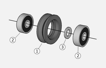
| 1 | EM-MW1 | V-wheel sleeve | 1 |
| 2 | EM-G5 | 5 x 16 x 5mm bearing | 2 |
| 3 | EM-W5P | 5mm precision washer | 1 |
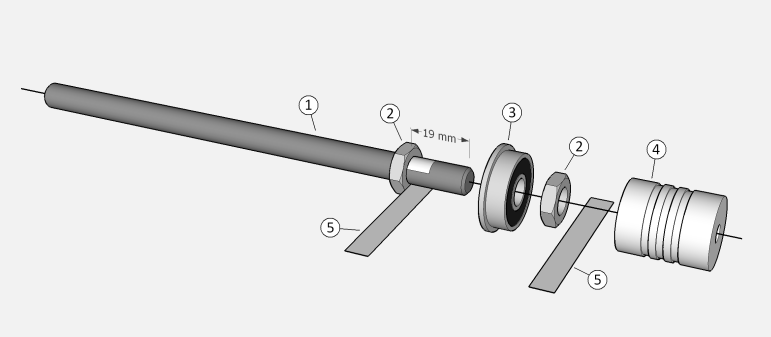
Lay one bearing on a flat surface. Push a V-wheel sleeve over it. The parts are designed to force-fit, so push firmly straight down. Thread this on a long M5 bolt, bearing side first, followed by a precision washer and the second bearing. Place the second bearing on a flat surface, and push the V-wheel sleeve over it too. Make sure both bearings are in as far as they will go. Remove the bolt.
Repeat 16 times (20 if you have the dual-X upgrade).
Step 2: Assemble the smooth idler wheels
| Item | Part Number | Part Description | Count |
|---|---|---|---|
| For each wheel | |||
| 1 | EM-MW2 | Smooth idler wheel sleeve | 1 |
| 2 | EM-G5 | 5 x 16 x 5mm bearing | 2 |
| 3 | EM-W5P | 5mm precision washer | 1 |
Lay one bearing on a flat surface. Push an idler wheel sleeve over it (lip up, of course). The parts are designed to force-fit, so push firmly straight down. Thread this on a long M5 bolt, lip side first, followed by a precision washer and the second bearing. Place the second bearing on a flat surface, and push the idler wheel sleeve over it too. Make sure the bearings are all the way in, with the first bearing resting against the lip of the sleeve. Remove the bolt.
Repeat 6 times.
Step 3: Mount the V-wheels on the right Y plate
| Item | Part Number | Part Description | Count |
|---|---|---|---|
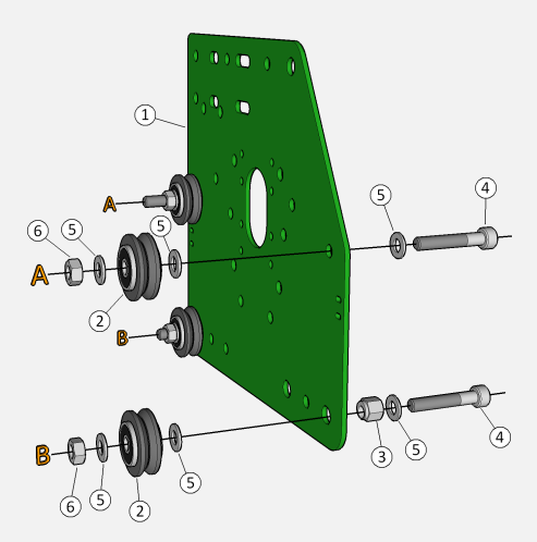
| 1 | EM-LMP | Motor mount plate | 1 |
| 2 | Assembled V-wheel | 4 | |
| 3 | EM-MES | Eccentric spacer | 2 |
| 4 | EM-S5-30 | M5 30mm cap screw | 4 |
| 5 | EM-W5 | M5 washer (form A) | 12 |
| 6 | EM-N5 | M5 hex nut | 4 |
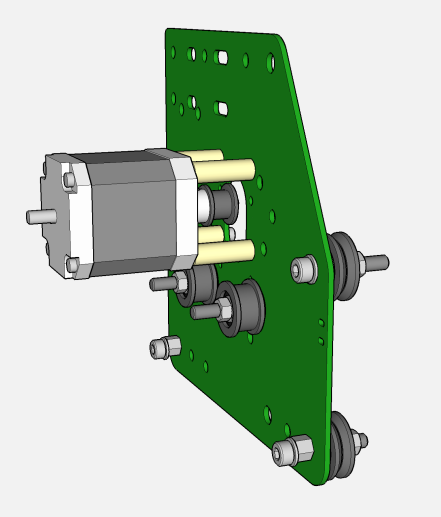
It may be a better idea to install the motor before anything else (see step 4 below).
The top wheels (marked A in the image) are fixed, the bottom ones (B) are adjustable. Put a washer on each bolt. For the bottom wheels, also add an eccentric spacer. Check the drawing for the correct orientation of the plate. Insert the bolts into the holes. Initially, position the eccentric spacers so that the top and bottom wheels are furthest apart (marked face toward the bottom). On each bolt, add a washer, a V-wheel, another washer, and a nut. Snug the nuts.
This is a good time to adjust the V-wheels. Slide the carriage on a piece of rail. Turn the eccentric spacers until the plate is held snugly, with no wobble, but still glides without excessive resistance. Tighten the bolts of the top V-wheels securely, readjust the eccentric spacers, and tighten the bottom V-wheels too. It's hard to describe how tight the eccentric spacers should be; there is some room for experimentation. As a guide, it should be very difficult to hold a V-wheel fixed with your fingers (to prevent it from turning) and slide the carriage on the rail.
Step 4: Mount the motor and the idlers on the right Y plate
| Item | Part Number | Part Description | Count |
|---|---|---|---|
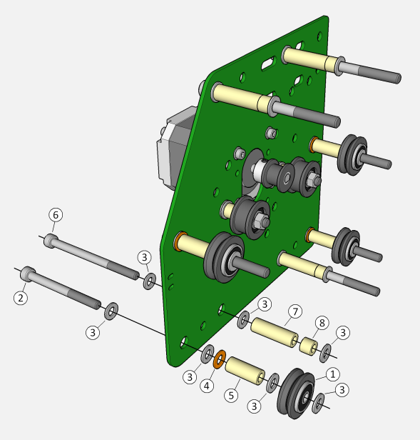
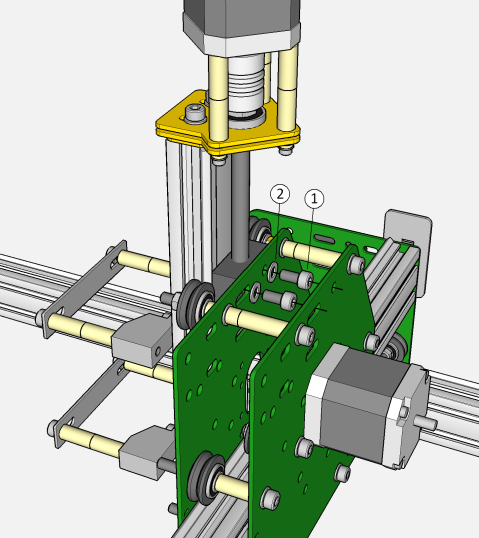
| 1 | Assembled idler wheel | 2 | |
| 2 | EM-S5-30 | M5 30mm cap screw | 2 |
| 3 | EM-W5 | M5 washer (form A) | 6 |
| 4 | EM-N5 | M5 hex nut | 2 |
| 5 | NEMA17 stepper motor | 1 | |
| 6 | EM-BP5 | 18-tooth MXL pulley 5mm bore | 1 |
| 7 | EM-S3-30 | M3 30mm cap screw | 4 |
| 8 | EM-W3 | M3 washer (form A) | 4 |
| 9 | EM-D3-15 | M3 23.81mm spacer | 4 |
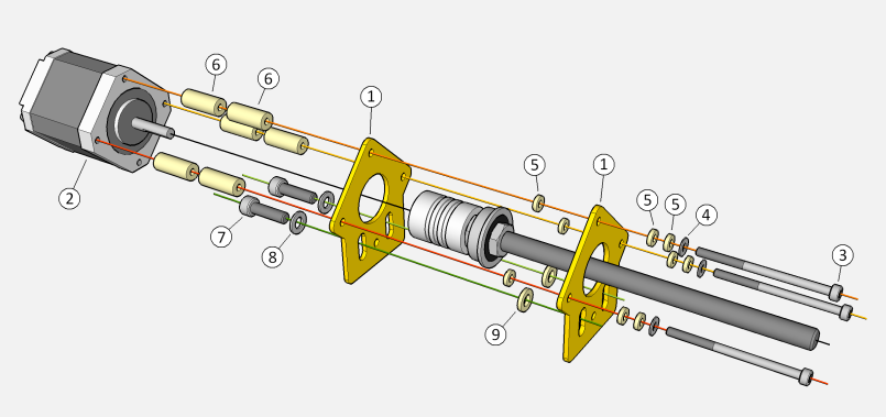
Please note that in some kits, the EM-D3-15 spacer is replaced by one EM-D3-12 spacer and three EM-W3N washers each.
Install the motor before anything else in steps 3 and 4. Images to be corrected and swapped. Put a washer on each M3 bolt. Hold the plate motor face down and and put the bolts in the holes. Place a flat object, such as a business card or a small flat plate, on top of the bolt heads, and using that object to hold the bolts in, turn the plate over. Lay the plate on the table and put the spacers (and washers, if applicable) on each bolt. Slide the plate to the edge of the table until one bolt is past the edge, holding that bolt from below. Bring the motor in position and twist that bolt in. No need to tighten: just enough so it doesn't fall out. Continue sliding the plate, doing one bolt at a time. Once all are in, snug all four bolts, then tighten one diagonal first, then the other.
The idlers are installed with the protruding bearing toward the plate.
Step 5: Assemble the left Y plate
5a. Dual Y drive
| Item | Part Number | Part Description | Count |
|---|---|---|---|
| EM-LMP | Motor mount plate | 1 | |
| Assembled V-wheel | 4 | ||
| EM-MES | Eccentric spacer | 2 | |
| Assembled idler wheel | 2 | ||
| EM-S5-30 | M5 30mm cap screw | 6 | |
| EM-W5 | M5 washer (form A) | 18 | |
| EM-N5 | M5 hex nut | 6 | |
| NEMA17 stepper motor | 1 | ||
| EM-BP5 | 18-tooth MXL pulley 5mm bore | 1 | |
| EM-S3-30 | M3 30mm cap screw | 4 | |
| EM-W3 | M3 washer (form A) | 4 | |
| EM-D3-15 | M3 23.81mm spacer | 4 |
Follow step 3 and step 4 instructions, with the motor plate flipped. The resulting assembly is a mirror image of the right Y plate.
5b. Single Y drive
| Item | Part Number | Part Description | Count |
|---|---|---|---|
| EM-LMP | Motor mount plate | 1 | |
| Assembled V-wheel | 4 | ||
| EM-MES | Eccentric spacer | 2 | |
| EM-S5-30 | M5 30mm cap screw | 4 | |
| EM-W5 | M5 washer (form A) | 12 | |
| EM-N5 | M5 hex nut | 4 |
Follow step 3 instructions, with the motor plate flipped. The resulting assembly is a mirror image of the right Y plate, but without the idlers and the motor.
