|
|
| (10 intermediate revisions by the same user not shown) |
| Line 1: |
Line 1: |
| − | During this step, you will assemble three motor plates:
| + | {{1.2 Motor Plate Assembly}} |
| − | * The rear side of the X carriage;
| |
| − | * The left side of the gantry (the left Y carriage);
| |
| − | * The right side of the gantry (the right Y carriage).
| |
| − | | |
| − | You need three of the four motor plates, the motors, the contents of Pack 3, and some parts from Packs 4 and 5.
| |
| − | | |
| − | Pack 3 contains the hardware and belt pulleys for both X and Y motors. The parts for the Y belt idler wheels are in Pack 4, and those for the X belt idlers in Pack 5.
| |
| − | | |
| − | Note that the left and right Y carriages must be mirror images of each other. As looking into the shaft of the motor, the left motor plate should have the cut-off corner on the left, and the right motor plate should have it on the right. The X motor plate can be positioned either way, but it is illustrated here with the cut-off corner on the left.
| |
| − | | |
| − | == Default Choices ==
| |
| − | | |
| − | {| class="wikitable" | |
| − | |-
| |
| − | !Motor size
| |
| − | !Rear plate for X carriage
| |
| − | !Left Y carriage
| |
| − | !Right Y carriage
| |
| − | |-
| |
| − | !NEMA 17
| |
| − | |Option A
| |
| − | |Option B
| |
| − | |Mirror image of option B
| |
| − | |-
| |
| − | !NEMA 23
| |
| − | |Option D (preferred) or E
| |
| − | |Option D
| |
| − | |Mirror image of option D
| |
| − | |}
| |
| − | | |
| − | <div class="noautonum">__TOC__</div>
| |
| − | | |
| − | == NEMA 17 Motors ==
| |
| − | | |
| − | There are three supported configurations for the motors, belts and idlers when
| |
| − | using NEMA 17 motors.
| |
| − | | |
| − | === A. Belt on top ===
| |
| − | | |
| − | {| | |
| − | |-
| |
| − | |[[File:EShapeoko_1.2_NEMA17_X_axis_belt_config_A.png|frame|none|x350px|NEMA 17 with belt configuration A on X Axis]]
| |
| − | |[[File:EShapeoko_1.2_NEMA17_Y_axis_belt_config_A.png|frame|none|x350px|NEMA 17 with belt configuration A on Y axis (showing the right Y carriage)]]
| |
| − | |}
| |
| − | | |
| − | This is the default configuration for the X axis. Extra parts are required
| |
| − | to implement it on the Y axis.
| |
| − | | |
| − | [[File:EShapeoko 1.2 assembly motor plate A F idlers.png|frame|none|Belt idler wheels]]
| |
| − | | |
| − | [[File:EShapeoko 1.2 assembly motor plate A motor.png|frame|none|Motor and belt pulley]]
| |
| − | | |
| − | [[File:EShapeoko 1.2 assembly motor plate A hole positions.png|frame|right|x231px|Hole positions for configuration A (red: motor; blue: idlers)]]
| |
| − | {| class="wikitable"
| |
| − | |-
| |
| − | !Item
| |
| − | !Part Number
| |
| − | !Part Description
| |
| − | !Count
| |
| − | |-
| |
| − | |1
| |
| − | |EM-LMP
| |
| − | |Motor mount plate
| |
| − | |1
| |
| − | |-
| |
| − | |2
| |
| − | |EM-S5-30
| |
| − | |M5 30mm cap screw
| |
| − | |2
| |
| − | |-
| |
| − | |3
| |
| − | |EM-W5
| |
| − | |M5 washer (form A)
| |
| − | |8
| |
| − | |-
| |
| − | |rowspan="3"|4
| |
| − | |EM-D5-04b
| |
| − | |M5 6.35mm aluminium spacer
| |
| − | |rowspan="3"|2
| |
| − | |-
| |
| − | !colspan="2"|<small>or</small>
| |
| − | |-
| |
| − | |EM-D5-04a
| |
| − | |M5 6.35mm nylon spacer (thick)
| |
| − | |-
| |
| − | |5
| |
| − | |
| |
| − | |Assembled idler wheel
| |
| − | |2
| |
| − | |-
| |
| − | |6
| |
| − | |EM-N5
| |
| − | |M5 hex nut
| |
| − | |2
| |
| − | |-
| |
| − | |7
| |
| − | |
| |
| − | |NEMA 17 stepper motor
| |
| − | |1
| |
| − | |-
| |
| − | |8
| |
| − | |EM-W3
| |
| − | |M3 washer (form A)
| |
| − | |4
| |
| − | |-
| |
| − | |9
| |
| − | |EM-S3-6
| |
| − | |M3 6mm cap screw
| |
| − | |4
| |
| − | |-
| |
| − | |10
| |
| − | |EM-BP5
| |
| − | |18-tooth MXL pulley 5mm bore
| |
| − | |1
| |
| − | |}
| |
| − | | |
| − | Install the idlers using 6.35 mm spacers in the holes shown. Orient them
| |
| − | with the protruding bearing closer to the motor plate.
| |
| − | | |
| − | Bolt the motor to the motor plate using the M3 screws, with one washer each.
| |
| − | Use the top NEMA 17 hole pattern.
| |
| − | | |
| − | Align the belt pulley with the idlers, and tighten the set screw firmly.
| |
| − | | |
| − | Note that the diagrams depict the rear X plate and the ''left'' Y carriage.
| |
| − | ''The right Y carriage is a mirror image'': it has the cut-off corner on
| |
| − | the opposite side.
| |
| − | | |
| − | === B. Belt on the outside, upper position ===
| |
| − | | |
| − | {|
| |
| − | |-
| |
| − | |[[File:EShapeoko_1.2_NEMA17_X_axis_belt_config_B.png|frame|none|x300px|NEMA 17 with belt configuration B on X Axis]]
| |
| − | |[[File:EShapeoko_1.2_NEMA17_Y_axis_belt_config_B.png|frame|none|x300px|NEMA 17 with belt configuration B on Y axis (showing the right Y carriage)]]
| |
| − | |}
| |
| − | | |
| − | This is the default configuration for the Y axis. Extra parts are required
| |
| − | to implement it on the X axis.
| |
| − | | |
| − | [[File:EShapeoko 1.2 assembly motor plate B idlers.png|frame|none|Belt idler wheels]]
| |
| − | | |
| − | [[File:EShapeoko 1.2 assembly motor plate B motor.png|frame|none|Motor and belt pulley]]
| |
| − | | |
| − | [[File:EShapeoko 1.2 assembly motor plate B hole positions.png|frame|right|x231px|Hole positions for configuration B (red: motor; blue: idlers)]]
| |
| − | {| class="wikitable"
| |
| − | |-
| |
| − | !Item
| |
| − | !Part Number
| |
| − | !Part Description
| |
| − | !Count
| |
| − | |-
| |
| − | |1
| |
| − | |EM-LMP
| |
| − | |Motor mount plate
| |
| − | |1
| |
| − | |-
| |
| − | |2
| |
| − | |EM-S5-30
| |
| − | |M5 30mm cap screw
| |
| − | |2
| |
| − | |-
| |
| − | |3
| |
| − | |EM-W5
| |
| − | |M5 washer (form A)
| |
| − | |6
| |
| − | |-
| |
| − | |4
| |
| − | |
| |
| − | |Assembled idler wheel
| |
| − | |2
| |
| − | |-
| |
| − | |5
| |
| − | |EM-N5
| |
| − | |M5 hex nut
| |
| − | |2
| |
| − | |-
| |
| − | |6
| |
| − | |
| |
| − | |NEMA17 stepper motor
| |
| − | |1
| |
| − | |-
| |
| − | |7
| |
| − | |EM-S3-30
| |
| − | |M3 30mm cap screw
| |
| − | |4
| |
| − | |-
| |
| − | |8
| |
| − | |EM-W3
| |
| − | |M3 washer (form A)
| |
| − | |4
| |
| − | |-
| |
| − | |9
| |
| − | |EM-D3-15
| |
| − | |M3 23.81mm spacer
| |
| − | |4
| |
| − | |-
| |
| − | |10
| |
| − | |EM-BP5
| |
| − | |18-tooth MXL pulley 5mm bore
| |
| − | |1
| |
| − | |}
| |
| − | | |
| − | Install the idlers with the protruding bearing toward the plate.
| |
| − | | |
| − | Install the motor in the top NEMA 17 hole pattern, as shown.
| |
| − | | |
| − | If you don't have a helping hand, this is one way to attach the motor
| |
| − | with just one pair. Put a washer on each M3 bolt. Hold the motor plate face down and
| |
| − | and put the bolts in the holes. Place a flat object, such as a business card or a
| |
| − | small flat plate, on top of the bolt heads, and using that object to hold the bolts in,
| |
| − | turn the plate over. Lay the plate on the table and put the spacers
| |
| − | on each bolt. Slide the plate to the edge of the table until one bolt
| |
| − | is past the edge, holding that bolt from below. Bring the motor in position and
| |
| − | twist that bolt in. No need to tighten: just enough so it doesn't fall out. Continue
| |
| − | sliding the plate, doing one bolt at a time. Once all are in, snug all four bolts,
| |
| − | then tighten one diagonal first, then the other.
| |
| − | | |
| − | Align the belt pulley with the belt idler wheels, and tighten the set
| |
| − | screw firmly.
| |
| − | | |
| − | Note that the diagrams depict the rear X plate and the ''left'' Y carriage.
| |
| − | ''The right Y carriage is a mirror image'': it has the cut-off corner on
| |
| − | the opposite side.
| |
| − | | |
| − | === C. Belt on the outside, lower position ===
| |
| − | | |
| − | {|
| |
| − | |-
| |
| − | |[[File:EShapeoko_1.2_NEMA17_X_axis_belt_config_C.png|frame|none|x300px|NEMA 17 with belt configuration C on X Axis]]
| |
| − | |[[File:EShapeoko_1.2_NEMA17_Y_axis_belt_config_C.png|frame|none|x300px|NEMA 17 with belt configuration C on Y axis (showing the right Y carriage)]]
| |
| − | |}
| |
| − | | |
| − | No extra parts are required for the Y axis. The same extra parts are required
| |
| − | to implement it on the X axis as option B above.
| |
| − | | |
| − | This configuration offers the best contact between the belt and the pulley.
| |
| − | | |
| − | [[File:EShapeoko 1.2 assembly motor plate C D idlers.png|frame|none|Belt idler wheels]]
| |
| − | | |
| − | [[File:EShapeoko 1.2 assembly motor plate C motor.png|frame|none|Motor and belt pulley]]
| |
| − | | |
| − | [[File:EShapeoko 1.2 assembly motor plate C hole positions.png|frame|right|x231px|Hole positions for configuration C (red: motor; blue: idlers)]]
| |
| − | {| class="wikitable"
| |
| − | |-
| |
| − | !Item
| |
| − | !Part Number
| |
| − | !Part Description
| |
| − | !Count
| |
| − | |-
| |
| − | |1
| |
| − | |EM-LMP
| |
| − | |Motor mount plate
| |
| − | |1
| |
| − | |-
| |
| − | |2
| |
| − | |EM-S5-30
| |
| − | |M5 30mm cap screw
| |
| − | |2
| |
| − | |-
| |
| − | |3
| |
| − | |EM-W5
| |
| − | |M5 washer (form A)
| |
| − | |6
| |
| − | |-
| |
| − | |4
| |
| − | |
| |
| − | |Assembled idler wheel
| |
| − | |2
| |
| − | |-
| |
| − | |5
| |
| − | |EM-N5
| |
| − | |M5 hex nut
| |
| − | |2
| |
| − | |-
| |
| − | |6
| |
| − | |
| |
| − | |NEMA17 stepper motor
| |
| − | |1
| |
| − | |-
| |
| − | |7
| |
| − | |EM-S3-30
| |
| − | |M3 30mm cap screw
| |
| − | |4
| |
| − | |-
| |
| − | |8
| |
| − | |EM-W3
| |
| − | |M3 washer (form A)
| |
| − | |4
| |
| − | |-
| |
| − | |9
| |
| − | |EM-D3-15
| |
| − | |M3 23.81mm spacer
| |
| − | |4
| |
| − | |-
| |
| − | |10
| |
| − | |EM-BP5
| |
| − | |18-tooth MXL pulley 5mm bore
| |
| − | |1
| |
| − | |}
| |
| − | | |
| − | Install the idlers with the protruding bearing toward the plate.
| |
| − | | |
| − | Install the motor in the bottom NEMA 17 hole pattern, as shown. See section
| |
| − | B above for a way to do this with just one pair of hands.
| |
| − | | |
| − | Align the belt pulley with the belt idler wheels, and tighten the set
| |
| − | screw firmly.
| |
| − | | |
| − | Note that the diagrams depict the rear X plate and the ''left'' Y carriage.
| |
| − | ''The right Y carriage is a mirror image'': it has the cut-off corner on
| |
| − | the opposite side.
| |
| − | | |
| − | == NEMA 23 Motors ==
| |
| − | | |
| − | There are three supported configurations for the motors, belts and idlers when
| |
| − | using NEMA 23 motors, and an additional one that's not described in detail here.
| |
| − | | |
| − | === D. Belts on the outside ===
| |
| − | | |
| − | {|
| |
| − | |-
| |
| − | |[[File:EShapeoko_1.2_NEMA23_X_axis_belt_config_D.png|frame|none|x300px|NEMA 23 with belt configuration D on X Axis]]
| |
| − | |[[File:EShapeoko_1.2_NEMA23_Y_axis_belt_config_D.png|frame|none|x300px|NEMA 23 with belt configuration D on Y axis (showing the right Y carriage)]]
| |
| − | |}
| |
| − | | |
| − | This is the default configuration for NEMA 23 motors on the Y axis,
| |
| − | and the preferred alternative for the X axis. No extra parts are required.
| |
| − | | |
| − | This configuration offers the best contact between the belt and the pulley.
| |
| − | | |
| − | [[File:EShapeoko 1.2 assembly motor plate C D idlers.png|frame|none|Belt idler wheels]]
| |
| − | | |
| − | [[File:EShapeoko 1.2 assembly motor plate D motor.png|frame|none|Motor and belt pulley]]
| |
| − | | |
| − | [[File:EShapeoko 1.2 assembly motor plate D hole positions.png|frame|right|x231px|Hole positions for configuration D (red: motor; blue: idlers)]]
| |
| − | {| class="wikitable"
| |
| − | |-
| |
| − | !Item
| |
| − | !Part Number
| |
| − | !Part Description
| |
| − | !Count
| |
| − | |-
| |
| − | |1
| |
| − | |EM-LMP
| |
| − | |Motor mount plate
| |
| − | |1
| |
| − | |-
| |
| − | |2
| |
| − | |EM-S5-30
| |
| − | |M5 30mm cap screw
| |
| − | |2
| |
| − | |-
| |
| − | |3
| |
| − | |EM-W5
| |
| − | |M5 washer (form A)
| |
| − | |14
| |
| − | |-
| |
| − | |4
| |
| − | |
| |
| − | |Assembled idler wheel
| |
| − | |2
| |
| − | |-
| |
| − | |5
| |
| − | |EM-N5
| |
| − | |M5 hex nut
| |
| − | |6
| |
| − | |-
| |
| − | |6
| |
| − | |
| |
| − | |NEMA23 stepper motor
| |
| − | |1
| |
| − | |-
| |
| − | |7
| |
| − | |EM-S5-40
| |
| − | |M5 40mm cap screw
| |
| − | |4
| |
| − | |-
| |
| − | |8
| |
| − | |EM-D5-16
| |
| − | |M5 25.4mm spacer
| |
| − | |4
| |
| − | |-
| |
| − | |9
| |
| − | |EM-BP6
| |
| − | |18-tooth MXL pulley 6.35mm bore
| |
| − | |1
| |
| − | |}
| |
| − | | |
| − | Install the idlers with the protruding bearing toward the plate.
| |
| − | | |
| − | Install the motor in the bottom NEMA 23 hole pattern, as shown.
| |
| − | | |
| − | If you don't have a helping hand, this is one way to attach the motor
| |
| − | with just one pair. Put a washer on each M5 bolt. Hold the motor plate face down and
| |
| − | and put the bolts in the holes. Place a flat object, such as a business card or a
| |
| − | small flat plate, on top of the bolt heads, and using that object to hold the bolts in,
| |
| − | turn the plate over. Lay the plate on the table and put the spacers
| |
| − | on each bolt. Place the motor in position over the bolts, and guide them
| |
| − | in. Place a washer and a nut on each bolt (no need to tighten: just enough so they
| |
| − | don't fall out). Snug all four bolts, then tighten one diagonal first, then the other.
| |
| − | | |
| − | Align the belt pulley with the belt idler wheels, and tighten the set
| |
| − | screw firmly.
| |
| − | | |
| − | Note that the diagrams depict the rear X plate and the ''left'' Y carriage.
| |
| − | ''The right Y carriage is a mirror image'': it has the cut-off corner on
| |
| − | the opposite side.
| |
| − | | |
| − | === E. Belts on top, lower position ===
| |
| − | | |
| − | {|
| |
| − | |-
| |
| − | |[[File:EShapeoko_1.2_NEMA23_X_axis_belt_config_E.png|frame|none|x350px|NEMA 23 with belt configuration E on X Axis]]
| |
| − | |[[File:EShapeoko_1.2_NEMA23_Y_axis_belt_config_E.png|frame|none|x350px|NEMA 23 with belt configuration E on Y axis (showing the right Y carriage)]]
| |
| − | |}
| |
| − | | |
| − | This is one of the alternatives for the X axis. Extra parts are required
| |
| − | to implement it on the Y axis.
| |
| − | | |
| − | This configuration is more compact than option D and has a lower centre of
| |
| − | gravity than option F, but it has the least contact between the belt and
| |
| − | the pulley.
| |
| − | | |
| − | [[File:EShapeoko 1.2 assembly motor plate E idlers.png|frame|none|Belt idler wheels]]
| |
| − | | |
| − | [[File:EShapeoko 1.2 assembly motor plate E motor.png|frame|none|Motor and belt pulley]]
| |
| − | | |
| − | [[File:EShapeoko 1.2 assembly motor plate E hole positions.png|frame|right|x231px|Hole positions for configuration E (red: motor; blue: idlers)]]
| |
| − | {| class="wikitable"
| |
| − | |-
| |
| − | !Item
| |
| − | !Part Number
| |
| − | !Part Description
| |
| − | !Count
| |
| − | |-
| |
| − | |1
| |
| − | |EM-LMP
| |
| − | |Motor mount plate
| |
| − | |1
| |
| − | |-
| |
| − | |2
| |
| − | |EM-S5-30F
| |
| − | |M5 30mm flanged button screw
| |
| − | |2
| |
| − | |-
| |
| − | |3
| |
| − | |EM-W5
| |
| − | |M5 washer (form A)
| |
| − | |14
| |
| − | |-
| |
| − | |rowspan="3"|4
| |
| − | |EM-D5-04b
| |
| − | |M5 6.35mm aluminium spacer
| |
| − | |rowspan="3"|2
| |
| − | |-
| |
| − | !colspan="2"|<small>or</small>
| |
| − | |-
| |
| − | |EM-D5-04a
| |
| − | |M5 6.35mm nylon spacer (thick)
| |
| − | |-
| |
| − | |5
| |
| − | |
| |
| − | |Assembled idler wheel
| |
| − | |2
| |
| − | |-
| |
| − | |6
| |
| − | |EM-N5
| |
| − | |M5 hex nut
| |
| − | |6
| |
| − | |-
| |
| − | |7
| |
| − | |
| |
| − | |NEMA23 stepper motor
| |
| − | |1
| |
| − | |-
| |
| − | |8
| |
| − | |EM-S5-18
| |
| − | |M5 18mm cap screw
| |
| − | |4
| |
| − | |-
| |
| − | |9
| |
| − | |EM-D5-02a
| |
| − | |M5 3.18mm spacer
| |
| − | |4
| |
| − | |-
| |
| − | |10
| |
| − | |EM-BP6
| |
| − | |18-tooth MXL pulley 6.35mm bore
| |
| − | |1
| |
| − | |}
| |
| − | | |
| − | Install the idlers using 6.35 mm spacers in the holes shown. Orient them
| |
| − | with the protruding bearing closer to the motor plate. Use
| |
| − | flanged button screws, not cap screws. Do not use a washer between
| |
| − | the screw head and the plate. For the X axis, two flanged button screws
| |
| − | can be found in Pack 3, and two cap screws in Pack 5 will remain unused.
| |
| − | | |
| − | Install the motor in the bottom NEMA 23 hole pattern, using 3.18mm spacers,
| |
| − | as shown. The spacers are just enough for the motor to clear the heads of
| |
| − | the idler wheel screws.
| |
| − | | |
| − | Note that the diagrams depict the rear X plate and the ''left'' Y carriage.
| |
| − | ''The right Y carriage is a mirror image'': it has the cut-off corner on
| |
| − | the opposite side.
| |
| − | | |
| − | === F. Belts on top, upper position ===
| |
| − | | |
| − | {|
| |
| − | |-
| |
| − | |[[File:EShapeoko_1.2_NEMA23_X_axis_belt_config_F.png|frame|none|x350px|NEMA 23 with belt configuration F on X Axis]]
| |
| − | |[[File:EShapeoko_1.2_NEMA23_Y_axis_belt_config_F.png|frame|none|x350px|NEMA 23 with belt configuration F on Y axis (showing the right Y carriage)]]
| |
| − | |}
| |
| − | | |
| − | This is one of the alternatives for the X axis, where it requires eight
| |
| − | extra M5 washers (EM-W5). Extra parts are required to implement it on the Y axis.
| |
| − | | |
| − | This configuration has better belt contact than option E, but a higher
| |
| − | centre of gravity. Note that older
| |
| − | machines may not have this hole pattern on their motor plates.
| |
| − | | |
| − | [[File:EShapeoko 1.2 assembly motor plate A F idlers.png|frame|none|Belt idler wheels]]
| |
| − | | |
| − | [[File:EShapeoko 1.2 assembly motor plate F motor.png|frame|none|Motor and belt pulley]]
| |
| − | | |
| − | [[File:EShapeoko 1.2 assembly motor plate F hole positions.png|frame|right|x231px|Hole positions for configuration F (red: motor; blue: idlers)]]
| |
| − | {| class="wikitable"
| |
| − | |-
| |
| − | !Item
| |
| − | !Part Number
| |
| − | !Part Description
| |
| − | !Count
| |
| − | |-
| |
| − | |1
| |
| − | |EM-LMP
| |
| − | |Motor mount plate
| |
| − | |1
| |
| − | |-
| |
| − | |2
| |
| − | |EM-S5-30
| |
| − | |M5 30mm cap screw
| |
| − | |2
| |
| − | |-
| |
| − | |3
| |
| − | |EM-W5
| |
| − | |M5 washer (form A)
| |
| − | |23
| |
| − | |-
| |
| − | |rowspan="3"|4
| |
| − | |EM-D5-04b
| |
| − | |M5 6.35mm aluminium spacer
| |
| − | |rowspan="3"|2
| |
| − | |-
| |
| − | !colspan="2"|<small>or</small>
| |
| − | |-
| |
| − | |EM-D5-04a
| |
| − | |M5 6.35mm nylon spacer (thick)
| |
| − | |-
| |
| − | |5
| |
| − | |
| |
| − | |Assembled idler wheel
| |
| − | |2
| |
| − | |-
| |
| − | |6
| |
| − | |EM-N5
| |
| − | |M5 hex nut
| |
| − | |6
| |
| − | |-
| |
| − | |7
| |
| − | |
| |
| − | |NEMA23 stepper motor
| |
| − | |1
| |
| − | |-
| |
| − | |8
| |
| − | |EM-S5-18
| |
| − | |M5 18mm cap screw
| |
| − | |3
| |
| − | |-
| |
| − | |rowspan="3"|9
| |
| − | |EM-S5-30F
| |
| − | |M5 30mm flanged button screw
| |
| − | |rowspan="3"|1
| |
| − | |-
| |
| − | !colspan="2"|<small>or</small>
| |
| − | |-
| |
| − | |EM-S5-16F
| |
| − | |M5 16mm flanged button screw
| |
| − | |-
| |
| − | |10
| |
| − | |EM-BP6
| |
| − | |18-tooth MXL pulley 6.35mm bore
| |
| − | |1
| |
| − | |}
| |
| − | | |
| − | Install the idlers using 6.35 mm spacers in the holes shown. Orient them
| |
| − | with the protruding bearing closer to the motor plate.
| |
| − | | |
| − | Install the motor in the upper NEMA 23 hole pattern, which is at a 45° angle.
| |
| − | Use two M5 washers on each screw between the motor and the plate. Use a flanged
| |
| − | button screw in the bottom mounting hole (Pack 3 contains two of EM-S5-30F).
| |
| − | Use regular cap screws in the other three holes. The bottom screw needs to be
| |
| − | lower profile to avoid fouling the MakerSlide.
| |
| − | | |
| − | Note that the diagrams depict the rear X plate and the ''left'' Y carriage.
| |
| − | ''The right Y carriage is a mirror image'': it has the cut-off corner on
| |
| − | the opposite side.
| |
| − | | |
| − | === G. Belts on the outside, alternate configuration ===
| |
| − | | |
| − | It is also possible to install the motor in the same position as
| |
| − | configuration D, but with the idlers (and half inch spacers) on the
| |
| − | lower two bolts holding the motor. The belt would go in the upper
| |
| − | side slot, same as configuration B. For this, you would need two
| |
| − | 12.7 mm spacers (not supplied).
| |
| | | | |
| | == Go To == | | == Go To == |
During this step, you will assemble three motor plates:
- The rear side of the X carriage;
- The left side of the gantry (the left Y carriage);
- The right side of the gantry (the right Y carriage).
You need three of the four motor plates, the motors, the contents of Pack 3, and some parts from Packs 4 and 5.
Pack 3 contains the hardware and belt pulleys for both X and Y motors. The parts for the Y belt idler wheels are in Pack 4, and those for the X belt idlers in Pack 5.
Note that the left and right Y carriages must be mirror images of each other. As looking into the shaft of the motor, the left motor plate should have the cut-off corner on the left, and the right motor plate should have it on the right. The X motor plate can be positioned either way, but it is illustrated here with the cut-off corner on the left.
The kits, as supplied, support only certain configurations. Other configurations are possible, and
are included for reference, but will require different fasteners and spacers. The stock kit contains
parts for these configurations:
| Motor size
|
Rear plate for X carriage
|
Left Y carriage
|
Right Y carriage
|
| NEMA 17
|
Option A
|
Option B
|
Mirror image of option B
|
| NEMA 23
|
Option D (preferred) or E
|
Option D
|
Mirror image of option D
|
An add-on kit is available with the parts for Options E and F.
NEMA 17 Motors
There are three supported configurations for the motors, belts and idlers when
using NEMA 17 motors.
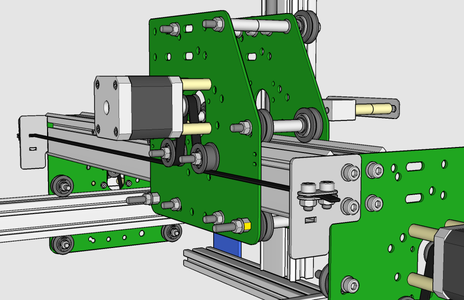
A. Belt on top
 NEMA 17 with belt configuration A on X Axis |
 NEMA 17 with belt configuration A on Y axis (showing the right Y carriage) |
This is the default configuration for the X axis. Extra parts are required
to implement it on the Y axis.

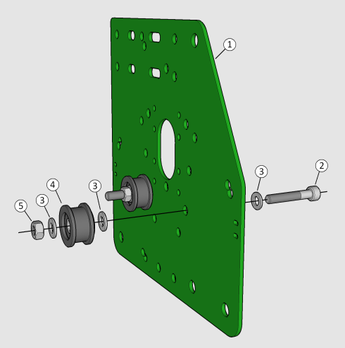
Belt idler wheels

Motor and belt pulley

Hole positions for configuration A (red: motor; blue: idlers)
| Item
|
Part Number
|
Part Description
|
Count
|
| 1
|
EM-LMP
|
Motor mount plate
|
1
|
| 2
|
EM-S5-30
|
M5 30mm cap screw
|
2
|
| 3
|
EM-W5
|
M5 washer (form A)
|
8
|
| 4
|
EM-D5-04b
|
M5 6.35mm aluminium spacer
|
2
|
| or
|
| EM-D5-04a
|
M5 6.35mm nylon spacer (thick)
|
| 5
|
|
Assembled idler wheel
|
2
|
| 6
|
EM-N5
|
M5 hex nut
|
2
|
| 7
|
|
NEMA 17 stepper motor
|
1
|
| 8
|
EM-W3
|
M3 washer (form A)
|
4
|
| 9
|
EM-S3-6
|
M3 6mm cap screw
|
4
|
| 10
|
EM-P2-20-5
|
20-tooth GT2 pulley 5mm bore
|
1
|
| or
|
| EM-BP5
|
18-tooth MXL pulley 5mm bore
|
Install the idlers using 6.35 mm spacers in the holes shown. Orient them
with the protruding bearing closer to the motor plate.
Bolt the motor to the motor plate using the M3 screws, with one washer each.
Use the top NEMA 17 hole pattern.
Align the belt pulley with the idlers, and tighten the set screw firmly.
Note that the diagrams depict the rear X plate and the left Y carriage.
The right Y carriage is a mirror image: it has the cut-off corner on
the opposite side.
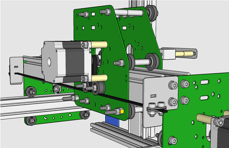
B. Belt on the outside, upper position
 NEMA 17 with belt configuration B on X Axis |
 NEMA 17 with belt configuration B on Y axis (showing the right Y carriage) |
This is the default configuration for the Y axis. Extra parts are required
to implement it on the X axis.
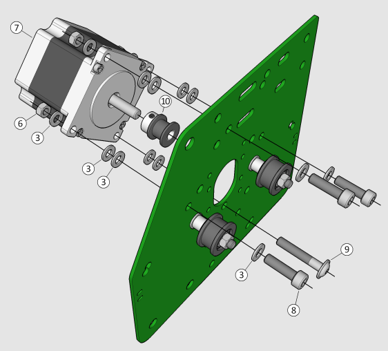
Belt idler wheels

Motor and belt pulley

Hole positions for configuration B (red: motor; blue: idlers)
| Item
|
Part Number
|
Part Description
|
Count
|
| 1
|
EM-LMP
|
Motor mount plate
|
1
|
| 2
|
EM-S5-30
|
M5 30mm cap screw
|
2
|
| 3
|
EM-W5
|
M5 washer (form A)
|
6
|
| 4
|
|
Assembled idler wheel
|
2
|
| 5
|
EM-N5
|
M5 hex nut
|
2
|
| 6
|
|
NEMA17 stepper motor
|
1
|
| 7
|
EM-S3-30
|
M3 30mm cap screw
|
4
|
| 8
|
EM-W3
|
M3 washer (form A)
|
4
|
| 9
|
EM-D3-15
|
M3 23.81mm spacer
|
4
|
| 10
|
EM-P2-20-5
|
20-tooth GT2 pulley 5mm bore
|
1
|
| or
|
| EM-BP5
|
18-tooth MXL pulley 5mm bore
|
Install the idlers with the protruding bearing toward the plate.
Install the motor in the top NEMA 17 hole pattern, as shown.
If you don't have a helping hand, this is one way to attach the motor
with just one pair. Put a washer on each M3 bolt. Hold the motor plate face down and
and put the bolts in the holes. Place a flat object, such as a business card or a
small flat plate, on top of the bolt heads, and using that object to hold the bolts in,
turn the plate over. Lay the plate on the table and put the spacers
on each bolt. Slide the plate to the edge of the table until one bolt
is past the edge, holding that bolt from below. Bring the motor in position and
twist that bolt in. No need to tighten: just enough so it doesn't fall out. Continue
sliding the plate, doing one bolt at a time. Once all are in, snug all four bolts,
then tighten one diagonal first, then the other.
Align the belt pulley with the belt idler wheels, and tighten the set
screw firmly.
Note that the diagrams depict the rear X plate and the left Y carriage.
The right Y carriage is a mirror image: it has the cut-off corner on
the opposite side.
C. Belt on the outside, lower position
 NEMA 17 with belt configuration C on X Axis |
 NEMA 17 with belt configuration C on Y axis (showing the right Y carriage) |
No extra parts are required for the Y axis. The same extra parts are required
to implement it on the X axis as option B above.
This configuration offers the best contact between the belt and the pulley.

Belt idler wheels

Motor and belt pulley

Hole positions for configuration C (red: motor; blue: idlers)
| Item
|
Part Number
|
Part Description
|
Count
|
| 1
|
EM-LMP
|
Motor mount plate
|
1
|
| 2
|
EM-S5-30
|
M5 30mm cap screw
|
2
|
| 3
|
EM-W5
|
M5 washer (form A)
|
6
|
| 4
|
|
Assembled idler wheel
|
2
|
| 5
|
EM-N5
|
M5 hex nut
|
2
|
| 6
|
|
NEMA17 stepper motor
|
1
|
| 7
|
EM-S3-30
|
M3 30mm cap screw
|
4
|
| 8
|
EM-W3
|
M3 washer (form A)
|
4
|
| 9
|
EM-D3-15
|
M3 23.81mm spacer
|
4
|
| 10
|
EM-P2-20-5
|
20-tooth GT2 pulley 5mm bore
|
1
|
| or
|
| EM-BP5
|
18-tooth MXL pulley 5mm bore
|
Install the idlers with the protruding bearing toward the plate.
Install the motor in the bottom NEMA 17 hole pattern, as shown. See section
B above for a way to do this with just one pair of hands.
Align the belt pulley with the belt idler wheels, and tighten the set
screw firmly.
Note that the diagrams depict the rear X plate and the left Y carriage.
The right Y carriage is a mirror image: it has the cut-off corner on
the opposite side.
NEMA 23 Motors
There are three supported configurations for the motors, belts and idlers when
using NEMA 23 motors, and an additional one that's not described in detail here.
D. Belts on the outside
 NEMA 23 with belt configuration D on X Axis |
 NEMA 23 with belt configuration D on Y axis (showing the right Y carriage) |
This is the default configuration for NEMA 23 motors on the Y axis,
and the preferred alternative for the X axis. No extra parts are required.
This configuration offers the best contact between the belt and the pulley.
Belt idler wheels

Motor and belt pulley

Hole positions for configuration D (red: motor; blue: idlers)
| Item
|
Part Number
|
Part Description
|
Count
|
| 1
|
EM-LMP
|
Motor mount plate
|
1
|
| 2
|
EM-S5-30
|
M5 30mm cap screw
|
2
|
| 3
|
EM-W5
|
M5 washer (form A)
|
14
|
| 4
|
|
Assembled idler wheel
|
2
|
| 5
|
EM-N5
|
M5 hex nut
|
6
|
| 6
|
|
NEMA23 stepper motor
|
1
|
| 7
|
EM-S5-40
|
M5 40mm cap screw
|
4
|
| 8
|
EM-D5-16
|
M5 25.4mm spacer
|
4
|
| 9
|
EM-P2-20-6
|
20-tooth GT2 pulley 6.35mm bore
|
1
|
| or
|
| EM-BP6
|
18-tooth MXL pulley 6.35mm bore
|
Install the idlers with the protruding bearing toward the plate.
Install the motor in the bottom NEMA 23 hole pattern, as shown.
If you don't have a helping hand, this is one way to attach the motor
with just one pair. Put a washer on each M5 bolt. Hold the motor plate face down and
and put the bolts in the holes. Place a flat object, such as a business card or a
small flat plate, on top of the bolt heads, and using that object to hold the bolts in,
turn the plate over. Lay the plate on the table and put the spacers
on each bolt. Place the motor in position over the bolts, and guide them
in. Place a washer and a nut on each bolt (no need to tighten: just enough so they
don't fall out). Snug all four bolts, then tighten one diagonal first, then the other.
Align the belt pulley with the belt idler wheels, and tighten the set
screw firmly.
Note that the diagrams depict the rear X plate and the left Y carriage.
The right Y carriage is a mirror image: it has the cut-off corner on
the opposite side.
E. Belts on top, lower position
 NEMA 23 with belt configuration E on X Axis |
 NEMA 23 with belt configuration E on Y axis (showing the right Y carriage) |
This is one of the alternatives for the X axis. Extra parts are required
to implement it on the Y axis.
This configuration is more compact than option D and has a lower centre of
gravity than option F, but it has the least contact between the belt and
the pulley.

Belt idler wheels

Motor and belt pulley

Hole positions for configuration E (red: motor; blue: idlers)
| Item
|
Part Number
|
Part Description
|
Count
|
| 1
|
EM-LMP
|
Motor mount plate
|
1
|
| 2
|
EM-S5-30F
|
M5 30mm flanged button screw
|
2
|
| 3
|
EM-W5
|
M5 washer (form A)
|
14
|
| 4
|
EM-D5-04b
|
M5 6.35mm aluminium spacer
|
2
|
| or
|
| EM-D5-04a
|
M5 6.35mm nylon spacer (thick)
|
| 5
|
|
Assembled idler wheel
|
2
|
| 6
|
EM-N5
|
M5 hex nut
|
6
|
| 7
|
|
NEMA23 stepper motor
|
1
|
| 8
|
EM-S5-18
|
M5 18mm cap screw
|
4
|
| 9
|
EM-D5-02a
|
M5 3.18mm spacer
|
4
|
| 10
|
EM-P2-20-6
|
20-tooth GT2 pulley 6.35mm bore
|
1
|
| or
|
| EM-BP6
|
18-tooth MXL pulley 6.35mm bore
|
Install the idlers using 6.35 mm spacers in the holes shown. Orient them
with the protruding bearing closer to the motor plate. Use
flanged button screws, not cap screws. Do not use a washer between
the screw head and the plate. For the X axis, two flanged button screws
can be found in Pack 3, and two cap screws in Pack 5 will remain unused.
Install the motor in the bottom NEMA 23 hole pattern, using 3.18mm spacers,
as shown. The spacers are just enough for the motor to clear the heads of
the idler wheel screws.
Note that the diagrams depict the rear X plate and the left Y carriage.
The right Y carriage is a mirror image: it has the cut-off corner on
the opposite side.
F. Belts on top, upper position
 NEMA 23 with belt configuration F on X Axis |
 NEMA 23 with belt configuration F on Y axis (showing the right Y carriage) |
This is one of the alternatives for the X axis, where it requires eight
extra M5 washers (EM-W5). Extra parts are required to implement it on the Y axis.
This configuration has better belt contact than option E, but a higher
centre of gravity. Note that older
machines may not have this hole pattern on their motor plates.
Belt idler wheels
Motor and belt pulley

Hole positions for configuration F (red: motor; blue: idlers)
| Item
|
Part Number
|
Part Description
|
Count
|
| 1
|
EM-LMP
|
Motor mount plate
|
1
|
| 2
|
EM-S5-30
|
M5 30mm cap screw
|
2
|
| 3
|
EM-W5
|
M5 washer (form A)
|
23
|
| 4
|
EM-D5-04b
|
M5 6.35mm aluminium spacer
|
2
|
| or
|
| EM-D5-04a
|
M5 6.35mm nylon spacer (thick)
|
| 5
|
|
Assembled idler wheel
|
2
|
| 6
|
EM-N5
|
M5 hex nut
|
6
|
| 7
|
|
NEMA23 stepper motor
|
1
|
| 8
|
EM-S5-18
|
M5 18mm cap screw
|
3
|
| 9
|
EM-S5-30F
|
M5 30mm flanged button screw
|
1
|
| or
|
| EM-S5-16F
|
M5 16mm flanged button screw
|
| 10
|
EM-P2-20-6
|
20-tooth GT2 pulley 6.35mm bore
|
1
|
| or
|
| EM-BP6
|
18-tooth MXL pulley 6.35mm bore
|
Install the idlers using 6.35 mm spacers in the holes shown. Orient them
with the protruding bearing closer to the motor plate.
Install the motor in the upper NEMA 23 hole pattern, which is at a 45° angle.
Use two M5 washers on each screw between the motor and the plate. Use a flanged
button screw in the bottom mounting hole (Pack 3 contains two of EM-S5-30F).
Use regular cap screws in the other three holes. The bottom screw needs to be
lower profile to avoid fouling the MakerSlide.
Note that the diagrams depict the rear X plate and the left Y carriage.
The right Y carriage is a mirror image: it has the cut-off corner on
the opposite side.
G. Belts on the outside, alternate configuration
It is also possible to install the motor in the same position as
configuration D, but with the idlers (and half inch spacers) on the
lower two bolts holding the motor. The belt would go in the upper
side slot, same as configuration B. For this, you would need two
12.7 mm spacers (not supplied).
Go To


