Difference between revisions of "EShapeoko 1.2 Assembly: Y carriages"
(Replaced content with "{{1.2 Y Carriages}} == Go To == * Next step: X rail * Previous step: X and Y motors * Back t...") |
|||
| (8 intermediate revisions by the same user not shown) | |||
| Line 1: | Line 1: | ||
| − | + | {{1.2 Y Carriages}} | |
| − | |||
| − | |||
| − | |||
| − | |||
| − | |||
| − | |||
| − | |||
| − | |||
| − | |||
| − | |||
| − | |||
| − | |||
| − | |||
| − | |||
| − | |||
| − | |||
| − | |||
| − | |||
| − | |||
| − | |||
| − | |||
| − | |||
| − | |||
| − | |||
| − | |||
| − | |||
| − | |||
| − | |||
| − | |||
| − | |||
| − | |||
| − | |||
| − | |||
| − | |||
| − | |||
| − | |||
| − | |||
| − | |||
| − | |||
| − | |||
| − | |||
| − | |||
| − | |||
| − | |||
| − | |||
| − | |||
| − | |||
| − | |||
| − | |||
| − | |||
| − | |||
| − | |||
| − | |||
| − | |||
| − | |||
| − | |||
| − | |||
| − | |||
| − | |||
| − | |||
| − | |||
| − | |||
| − | |||
| − | |||
| − | |||
| − | |||
| − | |||
| − | |||
| − | |||
| − | |||
| − | |||
| − | |||
| − | |||
| − | |||
== Go To == | == Go To == | ||
| − | * Next step: X | + | * Next step: [[EShapeoko 1.2 Assembly: X rail|X rail]] |
* Previous step: [[EShapeoko 1.2 Assembly: X and Y motors|X and Y motors]] | * Previous step: [[EShapeoko 1.2 Assembly: X and Y motors|X and Y motors]] | ||
* Back to [[EShapeoko 1.2 Assembly Instructions|assembly top page]] | * Back to [[EShapeoko 1.2 Assembly Instructions|assembly top page]] | ||
Latest revision as of 22:53, 22 January 2016
During this step, you will assemble two carriages:
- The left Y carriage;
- The right Y carriage.
You will need two of the motor plates you have assembled in the previous step (mirror images of each other), and the remaining parts from Pack 4.
| Item | Part Number | Part Description | Count |
|---|---|---|---|
| For each carriage | |||
| 1 | EM-S5-30 | M5 30mm cap screw | 4 |
| 2 | EM-W5 | M5 washer (form A) | 12 |
| 3 | EM-MES | Eccentric spacer | 2 |
| 4 | Assembled V-wheel | 4 | |
| 5 | EM-N5 | M5 hex nut | 4 |
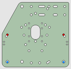
Check the drawing for the correct orientation of the plate: regardless of the motor and idler configuration, the V-wheels should be on the opposite side of the motor. The drawing shows the left Y carriage; the right Y carriage is a mirror image.
The top wheels (marked A in the image) are fixed, the bottom ones (B) are adjustable. Put a washer on each bolt. For the bottom wheels, also add an eccentric spacer. Insert the bolts into the holes. For the top wheels, use the top half of the hole (further away from the adjustable wheels, and from the edge of the plate — see hole position diagram). Initially, position the eccentric spacers so that the top and bottom wheels are furthest apart (marked face toward the bottom). On each bolt, add a washer, a V-wheel, another washer, and a nut. Snug the nuts.
If you have limit switches, install them now. It will be more difficult later, with the carriage riding on the rail.
This is a good time to adjust the V-wheels. Slide the carriage on a piece of rail. Turn the eccentric spacers until the plate is held snugly, with no wobble, but still glides without excessive resistance. Tighten the bolts of the top V-wheels securely, readjust the eccentric spacers, and tighten the bottom V-wheels too. It's hard to describe how tight the eccentric spacers should be; there is some room for experimentation. As a guide, it should be difficult to hold a V-wheel fixed with your fingers (to prevent it from turning) and slide the carriage on the rail.
You can leave the rail in. The rail should have the single T-slot between the Vs at the bottom, although this is not essential.
Repeat for the right Y carriage.
Set them aside for now.
Go To
- Next step: X rail
- Previous step: X and Y motors
- Back to assembly top page

