Difference between revisions of "GAUPS 1.1 Instructions"
m |
|||
| (21 intermediate revisions by the same user not shown) | |||
| Line 1: | Line 1: | ||
| − | |||
| − | |||
== Open Source == | == Open Source == | ||
| Line 6: | Line 4: | ||
GAUPS is open-source hardware, released under the Creative Commons Attribution-ShareAlike 4.0 License. KiCAD files will be available here soon. | GAUPS is open-source hardware, released under the Creative Commons Attribution-ShareAlike 4.0 License. KiCAD files will be available here soon. | ||
| + | |||
| + | [[File:GAUPS_1.1_stepper_shield_complete_system.jpg|center|600px|thumb|Nearly complete eShapeoko electronics with GAUPS 1.1 and Arduino Uno]] | ||
== Assembly == | == Assembly == | ||
| Line 19: | Line 19: | ||
!rowspan="2" | 1 | !rowspan="2" | 1 | ||
|[[File:GAUPS_1.0_R1.jpg|200px|center]] | |[[File:GAUPS_1.0_R1.jpg|200px|center]] | ||
| − | |rowspan="2" | [[File:GAUPS_1. | + | |rowspan="2" | [[File:GAUPS_1.1_Assembly_01_R1.jpg|450px]] |
|- | |- | ||
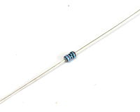
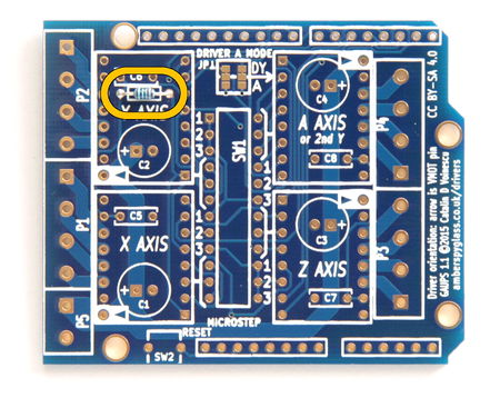
|Solder R1 (10 kΩ resistor). Color code: [[File:Ra.png|link=]][[File:Rb1.png|link=]][[File:Rc.png|link=]][[File:Rd0.png|link=]][[File:Re.png|link=]][[File:Rd0.png|link=]][[File:Re.png|link=]][[File:Rd2.png|link=]][[File:Rf.png|link=]][[File:Rb1.png|link=]][[File:Rg.png|link=]] (1%) or [[File:Ra.png|link=]][[File:Rb1.png|link=]][[File:Rc.png|link=]][[File:Rd0.png|link=]][[File:Re.png|link=]][[File:Rd3.png|link=]][[File:Rf.png|link=]][[File:RbG.png|link=]][[File:Rg.png|link=]] (5%). | |Solder R1 (10 kΩ resistor). Color code: [[File:Ra.png|link=]][[File:Rb1.png|link=]][[File:Rc.png|link=]][[File:Rd0.png|link=]][[File:Re.png|link=]][[File:Rd0.png|link=]][[File:Re.png|link=]][[File:Rd2.png|link=]][[File:Rf.png|link=]][[File:Rb1.png|link=]][[File:Rg.png|link=]] (1%) or [[File:Ra.png|link=]][[File:Rb1.png|link=]][[File:Rc.png|link=]][[File:Rd0.png|link=]][[File:Re.png|link=]][[File:Rd3.png|link=]][[File:Rf.png|link=]][[File:RbG.png|link=]][[File:Rg.png|link=]] (5%). | ||
| Line 25: | Line 25: | ||
!rowspan="2" | 2 | !rowspan="2" | 2 | ||
|[[File:GAUPS_1.0_SW1.jpg|200px|center]] | |[[File:GAUPS_1.0_SW1.jpg|200px|center]] | ||
| − | |rowspan="2" | [[File:GAUPS_1. | + | |rowspan="2" | [[File:GAUPS_1.1_Assembly_02_SW1.jpg|450px]] |
|- | |- | ||
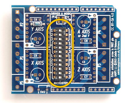
|Solder SW1 (12-way DIP switch). Orient it numbers to the left, "ON" text in the upper-right corner. The 1, 2 and 3 labels will match the 1, 2 and 3 silkscreen labels for the A axis. | |Solder SW1 (12-way DIP switch). Orient it numbers to the left, "ON" text in the upper-right corner. The 1, 2 and 3 labels will match the 1, 2 and 3 silkscreen labels for the A axis. | ||
| Line 31: | Line 31: | ||
!rowspan="2" | 3 | !rowspan="2" | 3 | ||
|[[File:GAUPS_1.0_SW2.jpg|200px|center]] | |[[File:GAUPS_1.0_SW2.jpg|200px|center]] | ||
| − | |rowspan="2" | [[File:GAUPS_1. | + | |rowspan="2" | [[File:GAUPS_1.1_Assembly_03_SW2.jpg|450px]] |
|- | |- | ||
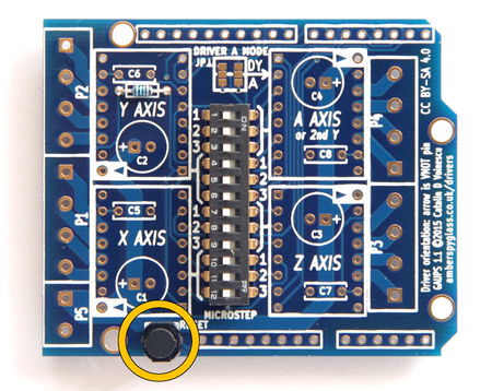
|Solder SW2 (push-button), taking care not to overheat it. | |Solder SW2 (push-button), taking care not to overheat it. | ||
| Line 37: | Line 37: | ||
!rowspan="2" | 4 | !rowspan="2" | 4 | ||
|[[File:GAUPS_1.0_C1-C4.jpg|200px|center]] | |[[File:GAUPS_1.0_C1-C4.jpg|200px|center]] | ||
| − | |rowspan="2" | [[File:GAUPS_1. | + | |rowspan="2" | [[File:GAUPS_1.1_Assembly_04_C1-C4.jpg|450px]] |
|- | |- | ||
|Solder C1, C2, C3, C4 (47 µF 35 V capacitors, or, in the 40 V version, 22 µF 50 V), paying attention to the orientation. Install with the negative terminal (shorter lead, marked with a stripe on the body of the capacitor) toward the middle of the board. | |Solder C1, C2, C3, C4 (47 µF 35 V capacitors, or, in the 40 V version, 22 µF 50 V), paying attention to the orientation. Install with the negative terminal (shorter lead, marked with a stripe on the body of the capacitor) toward the middle of the board. | ||
| Line 43: | Line 43: | ||
!rowspan="2" | 5 | !rowspan="2" | 5 | ||
|[[File:GAUPS_1.0_C5-C8.jpg|200px|center]] | |[[File:GAUPS_1.0_C5-C8.jpg|200px|center]] | ||
| − | |rowspan="2" | [[File:GAUPS_1. | + | |rowspan="2" | [[File:GAUPS_1.1_Assembly_05_C5-C8.jpg|450px]] |
|- | |- | ||
|Solder C5, C6, C7, C8 (100 nF capacitors). These are not polarized, so orientation doesn't matter. | |Solder C5, C6, C7, C8 (100 nF capacitors). These are not polarized, so orientation doesn't matter. | ||
| Line 49: | Line 49: | ||
!rowspan="2" | 6 | !rowspan="2" | 6 | ||
|[[File:GAUPS_1.0_U1-U4.jpg|200px|center]] | |[[File:GAUPS_1.0_U1-U4.jpg|200px|center]] | ||
| − | |rowspan="2" | [[File:GAUPS_1. | + | |rowspan="2" | [[File:GAUPS_1.1_Assembly_06_U1-U4.jpg|450px]] |
|- | |- | ||
|Solder the eight 8-way female headers for the drivers. | |Solder the eight 8-way female headers for the drivers. | ||
|- | |- | ||
!rowspan="2" | 7 | !rowspan="2" | 7 | ||
| − | |[[File:GAUPS_1. | + | |[[File:GAUPS_1.1_J1-J4.jpg|300px|center]] |
| − | |rowspan="2" | [[File:GAUPS_1. | + | |rowspan="2" | [[File:GAUPS_1.1_Assembly_07_J1-J4.jpg|450px]] |
|- | |- | ||
|Solder the 6-way, two 8-way, and one 10-way Arduino stacking headers, taking care to not to deposit solder on the long pins (except where they meet the PCB, of course). Make sure the pins are straight and parallel before soldering them. | |Solder the 6-way, two 8-way, and one 10-way Arduino stacking headers, taking care to not to deposit solder on the long pins (except where they meet the PCB, of course). Make sure the pins are straight and parallel before soldering them. | ||
| Line 61: | Line 61: | ||
!rowspan="2" | 8 | !rowspan="2" | 8 | ||
|align="center" | [[File:GAUPS_1.0_J1,_J2,_J5_apart.jpg|200px]][[File:GAUPS_1.0_J3,_J4_apart.jpg|200px]]<br />[[File:GAUPS_1.0_J1,_J2,_J5_joined.jpg|200px]][[File:GAUPS_1.0_J3,_J4_joined.jpg|200px]] | |align="center" | [[File:GAUPS_1.0_J1,_J2,_J5_apart.jpg|200px]][[File:GAUPS_1.0_J3,_J4_apart.jpg|200px]]<br />[[File:GAUPS_1.0_J1,_J2,_J5_joined.jpg|200px]][[File:GAUPS_1.0_J3,_J4_joined.jpg|200px]] | ||
| − | |rowspan="2" | [[File:GAUPS_1. | + | |rowspan="2" | [[File:GAUPS_1.1_Assembly_08_P1-P5.jpg|450px]] |
|- | |- | ||
|Join one 2-way and two 4-way screw terminals, by sliding the little dovetails into the slots. Solder them as P5, P1 and P2, with the openings for the wires toward the outside of the board. Join the remaining two 4-way screw terminals. Solder them as P3 and P4. Check all the soldering, remove any loose bits of solder, insert into the Arduino Uno, and you're done! | |Join one 2-way and two 4-way screw terminals, by sliding the little dovetails into the slots. Solder them as P5, P1 and P2, with the openings for the wires toward the outside of the board. Join the remaining two 4-way screw terminals. Solder them as P3 and P4. Check all the soldering, remove any loose bits of solder, insert into the Arduino Uno, and you're done! | ||
| Line 68: | Line 68: | ||
== Driver Orientation == | == Driver Orientation == | ||
| − | '''Please pay attention to driver orientation!''' A driver inserted backwards will be destroyed instantly when the power is turned on. | + | {{warning|'''Please pay attention to driver orientation!''' A driver inserted backwards will be destroyed instantly when the power is turned on.}} |
Driver pin VMOT (motor supply voltage) is marked with an arrow on the silkscreen (please note that this is different from the beta version). The motor outputs (1A, 1B, 2A, 2B) face the respective screw terminals. The electrolytic capacitor is near the VMOT pin, and the yellow ceramic capacitor is near the VDD pin. The digital inputs are toward the middle of the board. | Driver pin VMOT (motor supply voltage) is marked with an arrow on the silkscreen (please note that this is different from the beta version). The motor outputs (1A, 1B, 2A, 2B) face the respective screw terminals. The electrolytic capacitor is near the VMOT pin, and the yellow ceramic capacitor is near the VDD pin. The digital inputs are toward the middle of the board. | ||
| − | + | {{warning|Two drivers (X and Y) are oriented one way, the other two (Z and A) the other way.}} | |
| + | |||
| + | {{warning|Adjust the motor current before applying power for the first time. The trimpots on the drivers do not come pre-set to any particular position. Please turn them down (almost all the way anti-clockwise) before applying power. Once you've applied power, increase the current carefully. On some Pololu drivers, the range of the trimpot exceeds the allowable value for the driver chip, and turning it too far clockwise can cause the chip to explode.}} | ||
== Solder Bridges == | == Solder Bridges == | ||
| + | [[File:GAUPS 1.1 A driver mode.jpg|170px|right|thumb|Solder bridges for A driver mode]] | ||
=== Dual-Y or 4-Axis Operation === | === Dual-Y or 4-Axis Operation === | ||
For Dual-Y operation, the A driver takes the same control signals (STEP and DIR) as the Y driver, acting as a second Y driver instead of a fourth independent axis. This is the default configuration, and you don't need to do anything to use it. | For Dual-Y operation, the A driver takes the same control signals (STEP and DIR) as the Y driver, acting as a second Y driver instead of a fourth independent axis. This is the default configuration, and you don't need to do anything to use it. | ||
| − | For 4-axis operation (or spindle relay in the A axis slot, instead of a driver), STEP and DIR for the A driver come from Arduino pins D12 and D13. | + | For 4-axis operation (or spindle relay in the A axis slot, instead of a driver), STEP and DIR for the A driver come from Arduino pins D12 and D13. In both columns, cut the trace joining the top and middle pad, and bridge the middle and bottom pad with solder. |
| − | |||
| − | |||
| − | |||
| − | |||
| − | |||
| − | |||
| − | |||
| − | |||
| − | |||
| − | |||
| − | |||
| − | |||
| − | |||
| − | |||
| − | |||
| − | |||
| − | |||
| − | |||
| − | |||
| − | |||
It is unlikely that you will need to change from the default configuration. As of yet, | It is unlikely that you will need to change from the default configuration. As of yet, | ||
| Line 106: | Line 89: | ||
modules are very rare. | modules are very rare. | ||
| + | [[File:GAUPS 1.1 logic power mode.jpg|170px|right|thumb|Solder bridges for logic voltage selection]] | ||
=== Supply Voltage === | === Supply Voltage === | ||
| − | By default, the board uses the IOREF pin available on all R3 boards. | + | By default, the board uses the IOREF pin available on all R3 Arduino boards. |
| + | The Arduino connects | ||
IOREF to either 5 V or 3.3 V, depending on which supply voltage it uses. For example, an | IOREF to either 5 V or 3.3 V, depending on which supply voltage it uses. For example, an | ||
| − | Arduino Uno connects IOREF to 5 V, | + | Arduino Uno connects IOREF to 5 V, while an Arduino Due connects it to 3.3 V. |
| − | For | + | For older Arduino boards that do not have an IOREF pin, you will have to bridge |
one of the 3.3 V or 5 V solder bridges on the back of the board, as applicable. To avoid | one of the 3.3 V or 5 V solder bridges on the back of the board, as applicable. To avoid | ||
disasters if the GAUPS is later plugged into an R3 Arduino, also cut the trace across the | disasters if the GAUPS is later plugged into an R3 Arduino, also cut the trace across the | ||
| Line 276: | Line 261: | ||
The motor power supply input is P5, the two bottom screw terminals in the block of ten on the left side of the board. Positive is next to the X axis motor terminals, negative at the bottom edge of the board. Please note that this is different from the beta version. The polarity is marked on the silkscreen on the back of the board (there was no room on the front). | The motor power supply input is P5, the two bottom screw terminals in the block of ten on the left side of the board. Positive is next to the X axis motor terminals, negative at the bottom edge of the board. Please note that this is different from the beta version. The polarity is marked on the silkscreen on the back of the board (there was no room on the front). | ||
| − | '''Do not make or break any connections while the board or the Arduino are powered.''' There is a high risk of destroying the drivers and/or the Arduino. | + | {{warning|'''Do not make or break any connections while the board or the Arduino are powered.''' There is a high risk of destroying the drivers and/or the Arduino.}} |
| − | [[File:GAUPS 1. | + | |
| + | [[File:GAUPS 1.1 wiring.jpg|none|600px|thumb|GAUPS 1.1 Example Configuration]] | ||
This image (click on it to enlarge) shows an example configuration: | This image (click on it to enlarge) shows an example configuration: | ||
* Four drivers and four motors | * Four drivers and four motors | ||
* Dual-Y (two Y motors, each with its own driver) | * Dual-Y (two Y motors, each with its own driver) | ||
| − | * | + | * Pololu DRV8825 purple high-current drivers (note that other driver modules may have the trimpot in a different location, so do not use it to decide the driver module orientation. Always check the pin labels). |
| − | + | * Heatsinks | |
| − | + | ||
| + | Note that the microstepping is not configured: the DIP switch is in its factory default configuration, corresponding to full stepping on all axes (not recommended). | ||
| − | [[File: | + | [[File:GAUPS 1.1 PCB Bottom.jpg|300px|right|thumb|Bottom of GAUPS 1.1 PCB, showing supply polarity]] |
Also, when using GRBL 0.8 or 0.9 with the "invert mask" set to 0, | Also, when using GRBL 0.8 or 0.9 with the "invert mask" set to 0, | ||
| − | Pololu | + | any Pololu drivers, and the motors we carry in our |
store, wired as shown, for a move in the positive direction of each | store, wired as shown, for a move in the positive direction of each | ||
axis, the motors turn as follows (as viewed looking into the shaft): | axis, the motors turn as follows (as viewed looking into the shaft): | ||
| Line 335: | Line 322: | ||
pins 3 and 4 another pair). | pins 3 and 4 another pair). | ||
| − | Also note that driver modules other than Pololu A4988 may turn the motors | + | Also note that driver modules other than Pololu A4988 and DRV8825 may turn the motors |
in the opposite direction, too, and the direction can also be changed in firmware. | in the opposite direction, too, and the direction can also be changed in firmware. | ||
| Line 370: | Line 357: | ||
|PCB | |PCB | ||
|1 | |1 | ||
| − | |GAUPS 1.1 PCB, dual-side 1.6 mm FR4, through-plated, ENIG, RoHS | + | |GAUPS 1.1 PCB, dual-side 1.6 mm FR4, 2 oz copper, through-plated, ENIG, RoHS |
|Amber Spyglass Ltd | |Amber Spyglass Ltd | ||
|— | |— | ||
| Line 453: | Line 440: | ||
== Schematic == | == Schematic == | ||
| − | [[File:GAUPS 1. | + | [[File:GAUPS 1.1 schematic.png|900px]] |
Revision as of 19:36, 16 April 2015
Open Source
GAUPS is derived from Bart Dring's open-source Buildlog.net Arduino-compatible Stepper Motor Driver Shield rev 3. Thank you, Bart!
GAUPS is open-source hardware, released under the Creative Commons Attribution-ShareAlike 4.0 License. KiCAD files will be available here soon.
Assembly
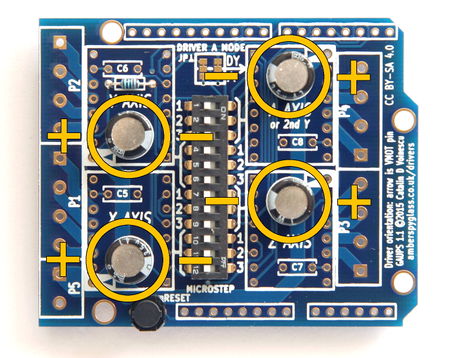
It's easiest to assemble the board in the order of component height, leaving the tallest last. For the parts with long leads, trim them as soon as you've soldered them (do not trim the Arduino headers, obviously). The instructions assume the board is held with the driver labels ("X AXIS" etc) the right way up, as shown.
Driver Orientation
| Warning: | Please pay attention to driver orientation! A driver inserted backwards will be destroyed instantly when the power is turned on. |
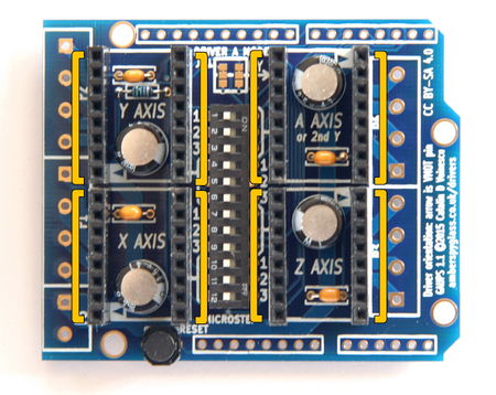
Driver pin VMOT (motor supply voltage) is marked with an arrow on the silkscreen (please note that this is different from the beta version). The motor outputs (1A, 1B, 2A, 2B) face the respective screw terminals. The electrolytic capacitor is near the VMOT pin, and the yellow ceramic capacitor is near the VDD pin. The digital inputs are toward the middle of the board.
| Warning: | Two drivers (X and Y) are oriented one way, the other two (Z and A) the other way. |
| Warning: | Adjust the motor current before applying power for the first time. The trimpots on the drivers do not come pre-set to any particular position. Please turn them down (almost all the way anti-clockwise) before applying power. Once you've applied power, increase the current carefully. On some Pololu drivers, the range of the trimpot exceeds the allowable value for the driver chip, and turning it too far clockwise can cause the chip to explode. |
Solder Bridges
Dual-Y or 4-Axis Operation
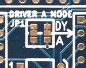
For Dual-Y operation, the A driver takes the same control signals (STEP and DIR) as the Y driver, acting as a second Y driver instead of a fourth independent axis. This is the default configuration, and you don't need to do anything to use it.
For 4-axis operation (or spindle relay in the A axis slot, instead of a driver), STEP and DIR for the A driver come from Arduino pins D12 and D13. In both columns, cut the trace joining the top and middle pad, and bridge the middle and bottom pad with solder.
It is unlikely that you will need to change from the default configuration. As of yet, GRBL supports only three axes, and spindle control relays in the form of Pololu-compatible modules are very rare.
Supply Voltage
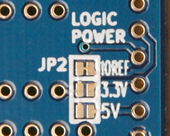
By default, the board uses the IOREF pin available on all R3 Arduino boards. The Arduino connects IOREF to either 5 V or 3.3 V, depending on which supply voltage it uses. For example, an Arduino Uno connects IOREF to 5 V, while an Arduino Due connects it to 3.3 V.
For older Arduino boards that do not have an IOREF pin, you will have to bridge one of the 3.3 V or 5 V solder bridges on the back of the board, as applicable. To avoid disasters if the GAUPS is later plugged into an R3 Arduino, also cut the trace across the IOREF solder bridge.
Since the R3 design has been the standard Arduino for a number of years, it is unlikely that you will need to make any changes.
Switch Settings
DIP switches are OFF to the left (the side of the switch with the numbers), ON to the right (the side labelled "ON").
Microstepping is controlled independently for each of the four drivers. Each driver has three switches associated with it. The silkscreen shows which switches apply to which driver.
| SW1 switch | A4988 and DRV8825 | A4988 | DRV8825 | DRV8834 | ||||||||||||||
|---|---|---|---|---|---|---|---|---|---|---|---|---|---|---|---|---|---|---|
| X axis | Y axis | Z axis | A axis | Pin name | 1 × | 2 × | 4 × | 8 × | 16 × | 16 × | 32 × | Pin name | 2 × | 4 × | 16 × | 32 × | ||
| 10 | 4 | 7 | 1 | MS1 | OFF | ON | OFF | ON | ON | OFF | ON | M0 | ON | OFF | ON | OFF | ||
| 11 | 5 | 8 | 2 | MS2 | OFF | OFF | ON | ON | ON | OFF | ON | M1 | OFF | OFF | ON | ON | ||
| 12 | 6 | 9 | 3 | MS3 | OFF | OFF | OFF | OFF | ON | ON | ON | (CFG) | not used | |||||
For instance, to set a DRV8825 driver on the Z axis to 8 × microstepping, set switches 7 on, 8 on, 9 off. In the Dual Y configuration, it's simplest to use the same type of driver and motor for both the Y axes (Y and A), and use the same microstepping configuration for both (switches 1–3 same as switches 4–6).
Note that it is not possible to select all microstepping combinations for the DRV8834 low-voltage stepper motor driver (1 × and 8 × would require pin M0 to be held low).
gShield/grblShield Compatibility
To make a GAUPS behave exactly like a gShield (or an older grblShield with the Z-axis hack), so that one can use the same settings for GRBL, set X and Y to 8 × microstepping, and Z to 2 ×:
| 1 | ON |
|---|---|
| 2 | ON |
| 3 | OFF |
| 4 | ON |
| 5 | ON |
| 6 | OFF |
| 7 | ON |
| 8 | OFF |
| 9 | OFF |
| 10 | ON |
| 11 | ON |
| 12 | OFF |
Connections
The motor screw terminals are connected to the driver outputs nearest to them, in the same order.
The motor power supply input is P5, the two bottom screw terminals in the block of ten on the left side of the board. Positive is next to the X axis motor terminals, negative at the bottom edge of the board. Please note that this is different from the beta version. The polarity is marked on the silkscreen on the back of the board (there was no room on the front).
| Warning: | Do not make or break any connections while the board or the Arduino are powered. There is a high risk of destroying the drivers and/or the Arduino. |
This image (click on it to enlarge) shows an example configuration:
- Four drivers and four motors
- Dual-Y (two Y motors, each with its own driver)
- Pololu DRV8825 purple high-current drivers (note that other driver modules may have the trimpot in a different location, so do not use it to decide the driver module orientation. Always check the pin labels).
- Heatsinks
Note that the microstepping is not configured: the DIP switch is in its factory default configuration, corresponding to full stepping on all axes (not recommended).
Also, when using GRBL 0.8 or 0.9 with the "invert mask" set to 0, any Pololu drivers, and the motors we carry in our store, wired as shown, for a move in the positive direction of each axis, the motors turn as follows (as viewed looking into the shaft):
| Axis | Motor | Axis Positive Direction | Motor Direction |
|---|---|---|---|
| X | Right | Counter-clockwise | |
| Y | Left (Y driver) | Toward the back | Counter-clockwise |
| Right (A driver) | Clockwise | ||
| Z | Up | Clockwise |
This is the standard direction of travel for a dual-motor dual-Y drive eShapeoko with any of the standard eShapeoko belt configurations (teeth down, belt going under the idler wheels and over the belt pulley). This is also valid for a Shapeoko with any of the belt mods that have the belt facing teeth down. For the original Shapeoko configuration (belt teeth up, going over the idler wheels and under the belt pulley) and any other teeth up configuration, reverse the direction of X and Y motors (by reversing the connections, black–green–blue–red instead of red–blue–green–black).
Note that not all motors from all manufacturers turn in the same direction when wired the same, although this seems to be the most common case. If your motor has different color wires, always determine the correct pairing before wiring the motors, to avoid damage to the drivers. Any configuration will work, as long as the wires in each pair are next to each other (pins 1 and 2 one pair, pins 3 and 4 another pair).
Also note that driver modules other than Pololu A4988 and DRV8825 may turn the motors in the opposite direction, too, and the direction can also be changed in firmware.
Power Supply
The choice of voltage depends on the driver modules. The kit of parts, as supplied, has capacitors rated at 35 V, so that's the maximum voltage. However, an alternative is supplied, with capacitors rated for 50 V. To keep the same form factor, these capacitors are smaller (22 µF instead of 47 µF).
With A4988 drivers, the maximum voltage is 35 V, but EMF induced in the motor during braking can raise the supply voltage, so we do not recommend using more than 30 V. The DRV8825 drivers are rated to 45 V, but, for the same reason, we do not recommend more than 40 V (provided that you are using capacitors rated 50 V or more).
A4988 and DRV8825 both work from 12 V, but the most popular voltage for them is 24 V. 19 V is also popular, because it's the typical voltage of a laptop power supply, and many people have one of those lying around.
The DRV8834 driver operates from 2.5 V to 10.8 V, so it's ideal for low-voltage applications.
Part List
| Part | Count | Description | Manufacturer | Part Number |
|---|---|---|---|---|
| PCB | 1 | GAUPS 1.1 PCB, dual-side 1.6 mm FR4, 2 oz copper, through-plated, ENIG, RoHS | Amber Spyglass Ltd | — |
| R1 | 1 | Resistor, 10 kΩ 0.125 W, metal film | Multicomp | MF12 10K |
| C1–C4 | 4 | Aluminium electrolytic capacitor, 47 µF 35 V, long life (5000 hours @ 105°C), radial, 2.5 mm lead spacing, ∅ 8 mm, 5 mm tall |
Rubycon | 35ML47MEFC8X5 |
| C5–C8 | 4 | Ceramic capacitor, 100 nF 50 V, X7R dielectric, 0.2" lead spacing | Multicomp | MCRR50104X7RK0050 |
| SW1 | 1 | Low-profile 12-way DIP switch, 0.1" pitch, 0.3" wide | Multicomp * | MCEI-12 |
| SW2 | 1 | Tactile switch, 6 mm | Panasonic | EVQPVG05K |
| U1–U4 | 8 | 8-way single-row female 0.1" pitch header, straight | Multicomp * | 2212S-08SG-85 |
| J1, J3 | 2 | 8-way single-row long pin (15 mm) female 0.1" pitch headers, straight | Samtec * | SSQ-108-04-F-S |
| J2 | 1 | 6-way single-row long pin (15 mm) female 0.1" pitch headers, straight | Samtec * | SSQ-106-04-F-S |
| J4 | 1 | 10-way single-row long pin (15 mm) female 0.1" pitch headers, straight | Samtec * | SSQ-110-04-F-S |
| P1–P4 | 4 | 4-way side-entry PCB screw terminal, 5 mm pitch | Camden Boss | CTB5202/4 |
| P5 | 1 | 2-way side-entry PCB screw terminal, 5 mm pitch | Camden Boss | CTB5202/2 |
For most components, numerous equivalent parts exist from various manufacturers. The given manufacturers and part numbers are just examples of compatible parts. However, except where marked with an asterisk, the supplied parts in our kit are exactly those listed here (those with an asterisk are generic equivalents). This is especially important for the long-life electrolytic capacitors of the correct form factor, and for the good quality screw terminals. Also important are the long (15 mm pins) Arduino headers; the typical Arduino headers with 10–12 mm pins are not tall enough for the solder joints on the back of the shield to clear the Arduino USB connector, and insulation is required.
We reserve the right to substitute parts without notice.

